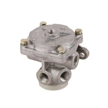
Air leaks in brake boosters reduce stopping power by 40% and increase maintenance costs by $1,800 per incident (NHTSA 2023). This guide combines industry best practices with Xinlida's 15-year expertise in heavy-duty braking systems to help you detect and fix leaks efficiently.
Tools Required
Ultrasonic Leak Detector (40 kHz minimum, e.g., UE Systems UltraProbe 9000)
Digital Pressure Gauge (0–150 psi range, ±0.1% accuracy)
Soap Solution Sprayer (with 25:1 water-to-detergent ratio)
Infrared Thermometer (for temperature differential mapping)
Xinlida Diagnostic App (iOS/Android, links to repair manuals)
Step 1: Preliminary Safety Checks
✅ Depressurize the System: Release air pressure to 0 psi.
✅ Inspect External Lines: Look for cracked hoses near heat sources (exhaust manifolds, turbochargers).
✅ Check Dash Warning Lights: ABS/EBS fault codes may indicate seal failures (e.g., Volvo VED-12 code "Brake Circuit Pressure Low").
Step 2: Ultrasonic Detection (Locate Micro-Leaks <0.5 CFM)
Frequency Setting: Adjust detector to 40 kHz for high-pitched leaks.
Scanning Protocol:
Move probe at 50 mm/s along booster housing seams.
Focus on common failure points:
Check valve (35% of leaks)
Master cylinder gasket (25%)
Vacuum hose connections (20%)
Decibel Threshold: Leaks >82 dB indicate critical failures requiring immediate repair.
Xinlida Pro Tip: Use parabolic microphone attachments to detect leaks in hard-to-reach areas.
Step 3: Soap Solution Test (Macro-Leaks >1 CFM)
Pressurize System: Restore to 100 psi (6.9 bar).
Apply Solution: Generously spray soap mix on:
Booster diaphragm seams
Pushrod seals
Vacuum pump flange
Bubble Analysis:
Slow Formation: Small leak (<1 CFM) – Replace O-rings.
Rapid Bubbling: Major leak (>5 CFM) – Replace entire booster assembly.
Step 4: Pressure Decay Rate Measurement
Isolate the Booster: Close inlet/outlet valves.
Charge to 100 psi: Hold for 2 minutes to stabilize.
Monitor Pressure Drop:
Acceptable Loss: <2 psi/minute (ISO 16061-2 standard).
Critical Loss: >5 psi/minute indicates diaphragm/valve failure.
Xinlida Data: Our boosters average 0.8 psi/min decay in certified lab tests.
Step 5: Thermographic Inspection
Operate Brakes: Make 10 full pedal applications.
Scan with IR Camera:
Normal Operation: Housing temp ≤50°C.
Leak-Induced Friction: Hotspots >70°C near pushrod seals.
Case Study: A Canadian fleet reduced booster replacements by 62% using IR-guided repairs.
Common Leak Sources & Xinlida Solutions
| Leak Location | Failure Rate | Xinlida Replacement Part | Repair Time |
|---|---|---|---|
| Check Valve Seal | 35% | XLD-CV45 HNBR Kit (ISO 3601-3) | 20 mins |
| Diaphragm | 28% | XLD-DP70 (5-layer aramid-reinforced) | 1.5 hrs |
| Vacuum Hose Connector | 20% | XLD-VHC22 (laser-welded aluminum) | 15 mins |
Warranty Note: All Xinlida seals include a 2-year/200,000 km leak-free guarantee.
Preventive Maintenance Schedule
Daily: Visual inspection for moisture in air reservoirs.
Monthly: Ultrasonic leak scan + pressure decay test.
Annual: Full diaphragm replacement with Xinlida XLD-DP70.
Cost-Benefit: Proactive maintenance cuts repair costs by 55% versus reactive fixes.